Folder Structure
The data used in the EvSLAM challenge can be downloaded via this link, and the folder structure is as follows:
  EvSLAM/
  |-- rosbag/
  |   `-- seq001.bag
  |   `-- seq002.bag
  |   `-- seq003.bag
  |   `-- seq004.bag
  |   `-- seq005.bag
  |   `-- seq006.bag
  |   `-- seq007.bag
  |   `-- test.bag
  |-- calibration/
  │   `-- calib_results_cam_drone.txt
  │   `-- calib_results_imu_drone.txt
  |   `-- calib_results_cam_others.txt
  |   `-- calib_results_imu_others.txt
  │   `-- calib_drone.bag
  |   `-- calib_others.bag
  |-- timestamps/
  │   `-- seq001_ref_time.txt
  │   `-- seq002_ref_time.txt
  │   `-- seq003_ref_time.txt
  │   `-- seq004_ref_time.txt
  │   `-- seq005_ref_time.txt
  │   `-- seq006_ref_time.txt
  │   `-- seq007_ref_time.txt
  |   `-- test_ref_time.txt
  |-- gt/
  │   `-- test_gt.txt
The rosbag folder contains the data bags for each sequence, the calibration folder contains the calibration files for different vehicles, the timestamps folder contains the timestamps associated with the trajectories we expect participants to provide, and the gt folder stores the ground truth data for the test sequences.
Data Format
'/dvxplorer_left/events':
(dvs_msgs/EventArray): Events from the left event camera.'/dvxplorer_right/events':
(dvs_msgs/EventArray): Events from the right event camera.'/dvxplorer_left/imu':
(sensor_msgs/Imu): Acceleration and angular velocity from IMU.'/camera/infra1/image_rect_raw/compressed':
(sensor_msgs/CompressedImage): Left-view grayscale images captured by the RealSense camera.'/camera/infra2/image_rect_raw/compressed':
(sensor_msgs/CompressedImage): Right-view grayscale images captured by the RealSense camera.'/camera/color/image_raw/compressed':
(sensor_msgs/CompressedImage): Color images captured by the RealSense camera.'/camera/depth/image_rect_raw/compressed':
(sensor_msgs/CompressedImage): Depth images captured by the RealSense camera.
Calibrations
- Common settings:
Camera model:pinhole+radtandistortion,
Resolution:640×480 '/dvxplorer_left/events'(cam0):
Extrinsics:T_cam_imu(IMU → cam0)
Intrinsics:[fx, fy, cx, cy]
Distortion:[k1, k2, p1, p2]
Overlaps:cam1–cam4
Time offset:timeshift_cam_imu'/dvxplorer_right/events'(cam1):
Extrinsics:T_cam_imu(IMU → cam1)
Intrinsics & distortion: same as common
Overlaps:cam0, cam2–cam4
Relative extrinsics:T_cn_cnm1(cam1 ← cam0)
Time offset:timeshift_cam_imu'/camera/color/image_raw/compressed'(cam2):
Extrinsics:T_cam_imu(IMU → cam2)
Intrinsics & distortion: same as common
Overlaps:cam0–cam1, cam3–cam4
Relative extrinsics:T_cn_cnm1(cam2 ← cam1)
Time offset:timeshift_cam_imu'/camera/infra1/image_rect_raw/compressed'(cam3):
Extrinsics:T_cam_imu(IMU → cam3)
Intrinsics & distortion: same as common
Overlaps:cam0–cam2, cam4
Relative extrinsics:T_cn_cnm1(cam3 ← cam2)
Time offset:timeshift_cam_imu'/camera/infra2/image_rect_raw/compressed'(cam4):
Extrinsics:T_cam_imu(IMU → cam4)
Intrinsics & distortion: same as common
Overlaps:cam0–cam3
Relative extrinsics:T_cn_cnm1(cam4 ← cam3)
Time offset:timeshift_cam_imu
The calibration format for calib_results_imu_XX.txt is as follows:
'/dvxplorer_left/imu':
Extrinsic calibration:T_i_b(IMU → body frame),
Accelerometer noise density:accelerometer_noise_density,
Accelerometer random walk:accelerometer_random_walk,
Gyroscope noise density:gyroscope_noise_density,
Gyroscope random walk:gyroscope_random_walk,
Model:model,
Time offset:time_offset,
Update rate:update_rateHz.
Sensor Suite
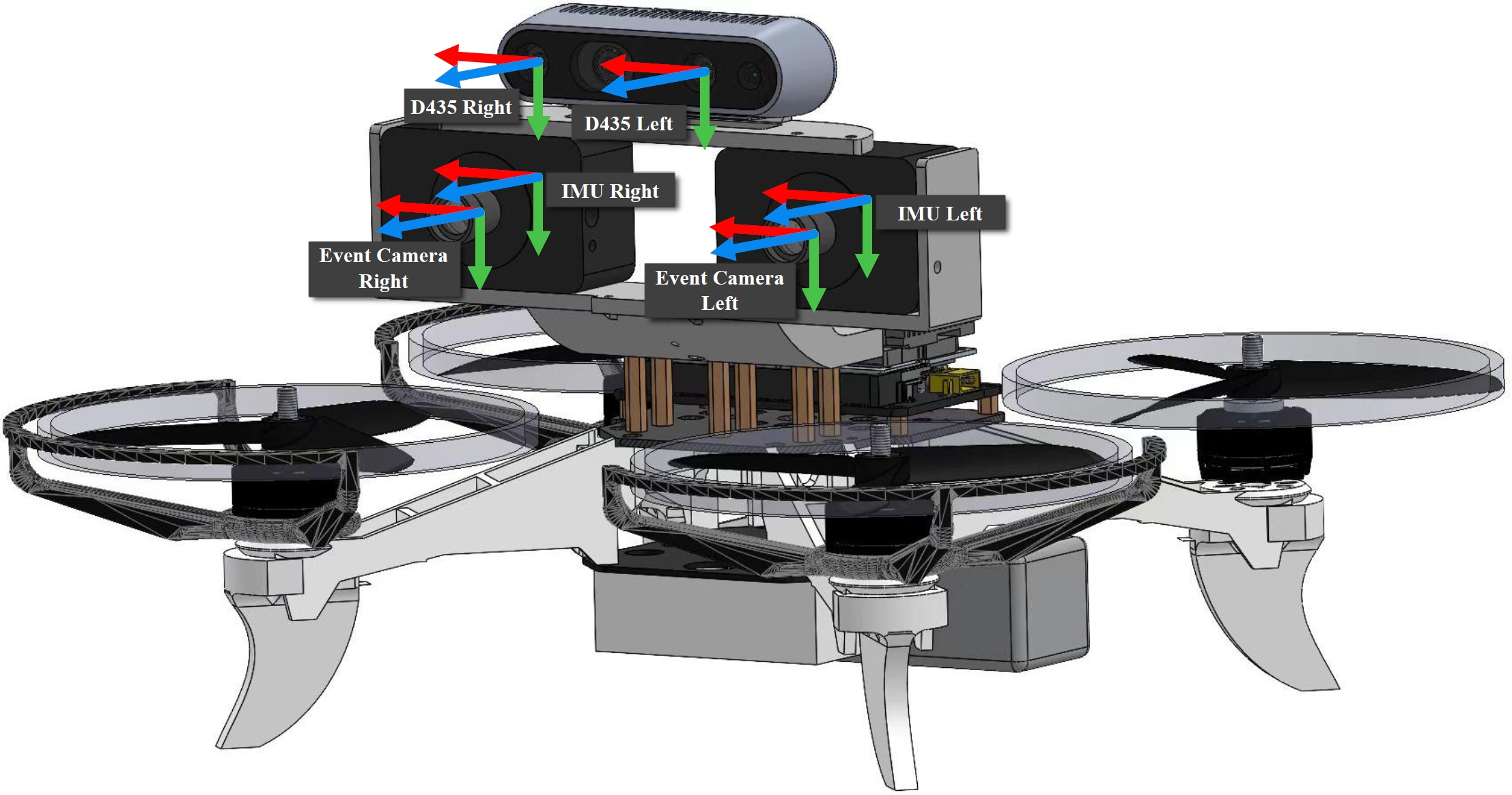
- Event cameras: x -> right, y -> down, z -> forward
- Frame-based Camera: x -> right, y -> down, z -> forward
- IMU: x -> right, y -> down, z -> forward
As illustrated in the figure, the coordinate systems of the sensors are defined as follows:
The specific sensor models and their parameters are shown in the table below:
| Sensor | Descriptison |
|---|---|
| Event Cameras |
2 x DVXplorer
640x480, 10cm baseline |
| Frame-based Camera | Intel RealSense D435
2 x 640x480 Grayscale, 5cm baseline, 30Hz, 1 x 640x480 RGB, 30Hz |
| IMU | Bosch BMI-160
800Hz |
| Motion Capture Device | NOKOV Mars26H 120Hz (for drone) and 60Hz (for others) |